Concepteur - Fabricant
de solutions de fixation innovantes
Clufix conjugue son expertise des fonctions d’assemblage et sa connaissance des processus industriels des équipementiers internationaux pour vous accompagner dans la réussite de vos projets.
Vous accompagner :
Sécuriser vos projets industriels
Notre accompagnement global sur mesure vous permet de vous concentrer pleinement sur votre cœur de métier. Vous bénéficiez de :
- la prise en compte de vos contraintes projets
- la garantie d’une pièce de fixation fonctionnelle
- la sécurisation et la simplification de toutes vos opérations dans le respect des délais
- une collaboration créatrice de valeur
Notre créativité vise à
Optimiser vos process d’assemblage
L’étude de cas industriels concrets nous guide dans le développement de nouveaux produits. Intégrez les solutions de fixation Innovantes de Clufix pour :
- gagner en productivité
- bénéficier d’un produit éprouvé
- améliorer la qualité de vos projets
- optimiser votre mix Qualité Coût Délai
Catalogue
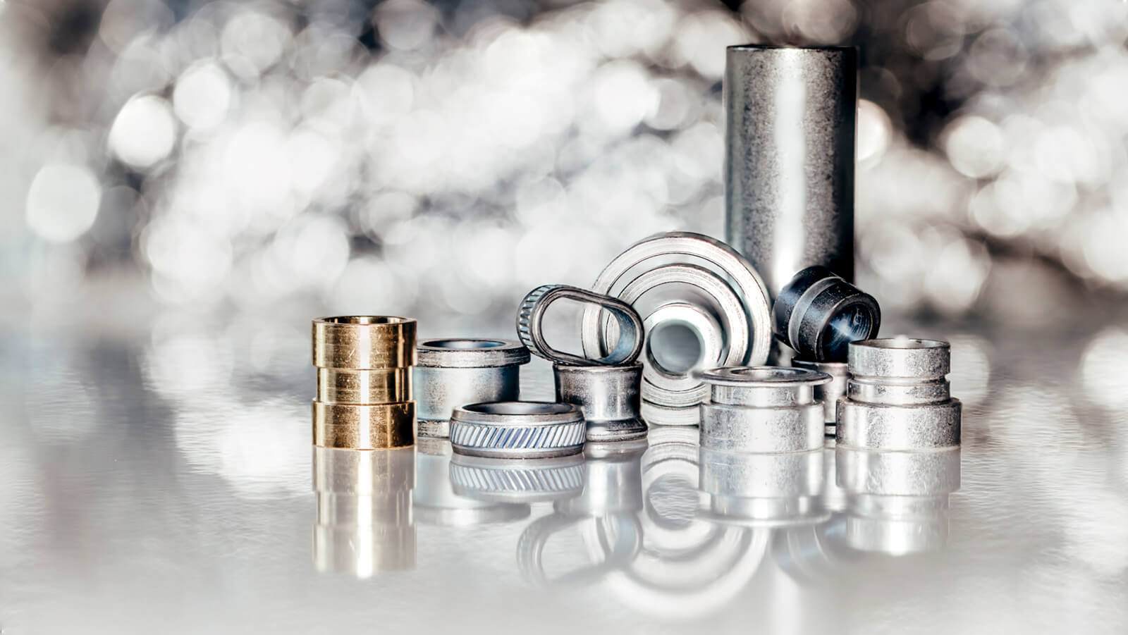
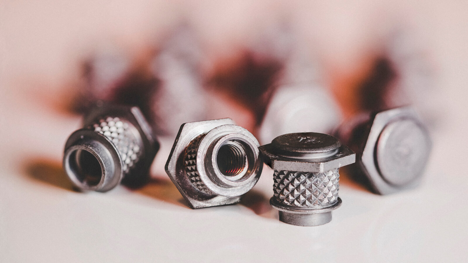
Nos solutions standard
Choisissez les pièces de fixation pour vos applications parmi plusieurs milliers de références au catalogue.
Vos avantages :
- un large choix de standards de la fixation
- l’assurance d’une fabrication et d’une finition de qualité
- des performances mécaniques fiables et répétables
Cas client
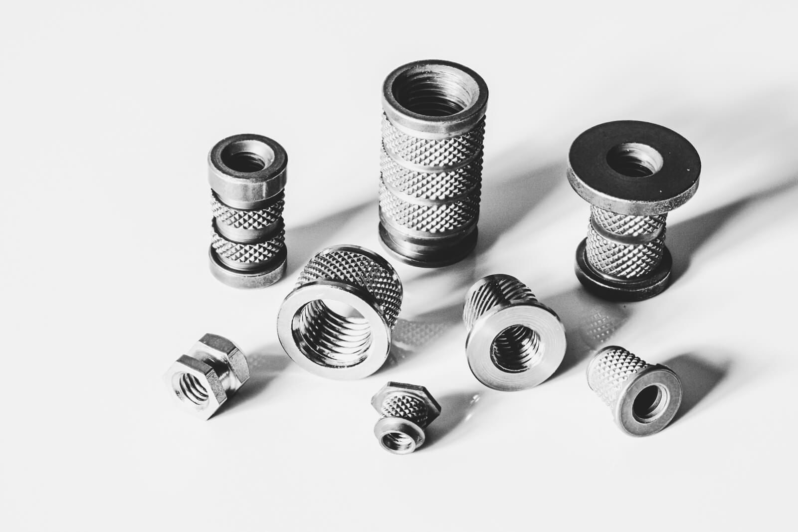
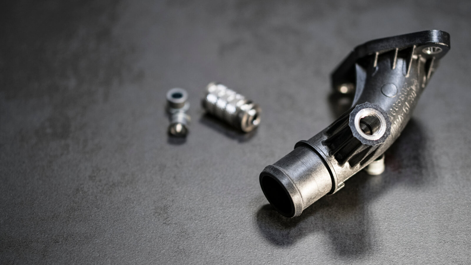
Insert M4 fluo-tourné
Application sur Adblue.
Découvrez comment le travail d’équipe a permis le développement d’une solution innovante répondant à l’exigence d’encombrement du client.

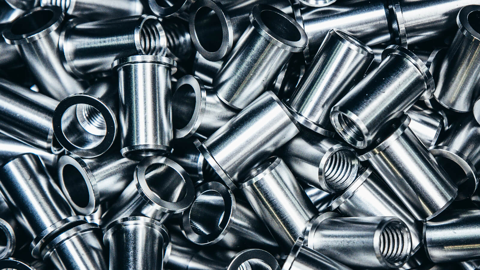
Cas client
Commande volant
Notre client équipementier international a fait confiance à Clufix pour la fourniture d’un insert taraudé M5 en Laiton pour les boitiers plastiques de commandes au volant pour toute la nouvelle gamme BMW.
Conseil et expertise ont conduit au succès de ce projet à destination de la Tunisie.
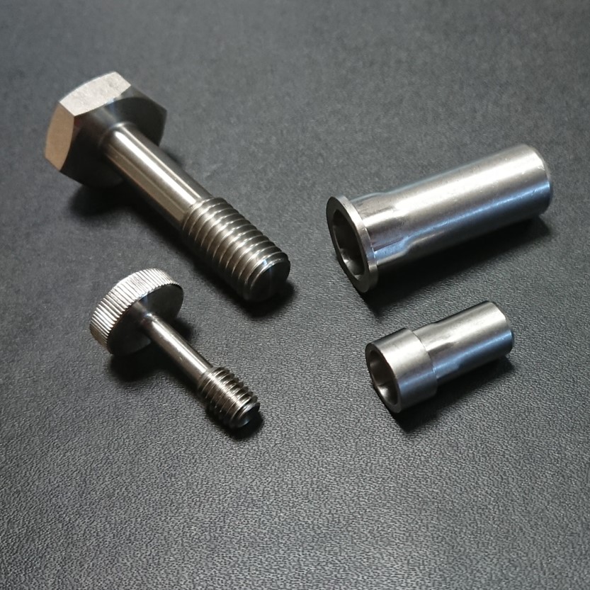
Cas client
Insert M12 pour sonde et limiteur frappé à froid
Clufix a su apporter tout son savoir-faire et son expertise pour orienter les choix techniques permettant une offre compétitive et robuste.

Solutions & Composants d’Assemblage